Service Types
Configuration Forms
A
Firmwareas defined in the previous section is a collection of services which will be run on a DAQAstra. Each service and associated configuration fields are defined in this section.
Table of Contents
- Analog Input
- Digital Input
- Frequency Counter
- Analog Output
- Digital Output
- PWM Output
- Complementary PWM
- Command
- Math Channel
- PID Controller
- Bang-Bang Controller
- Stepper Motor
- Actuator
- Stateful Actuator
- IMU (MPU6050)
- Magnetometer (QMC5883L)
- IR Camera (MLX90640)
- Thermocouple (MAX31855)
- Load Cell (HX711)
- ADS7953
- Power-Distribution Unit
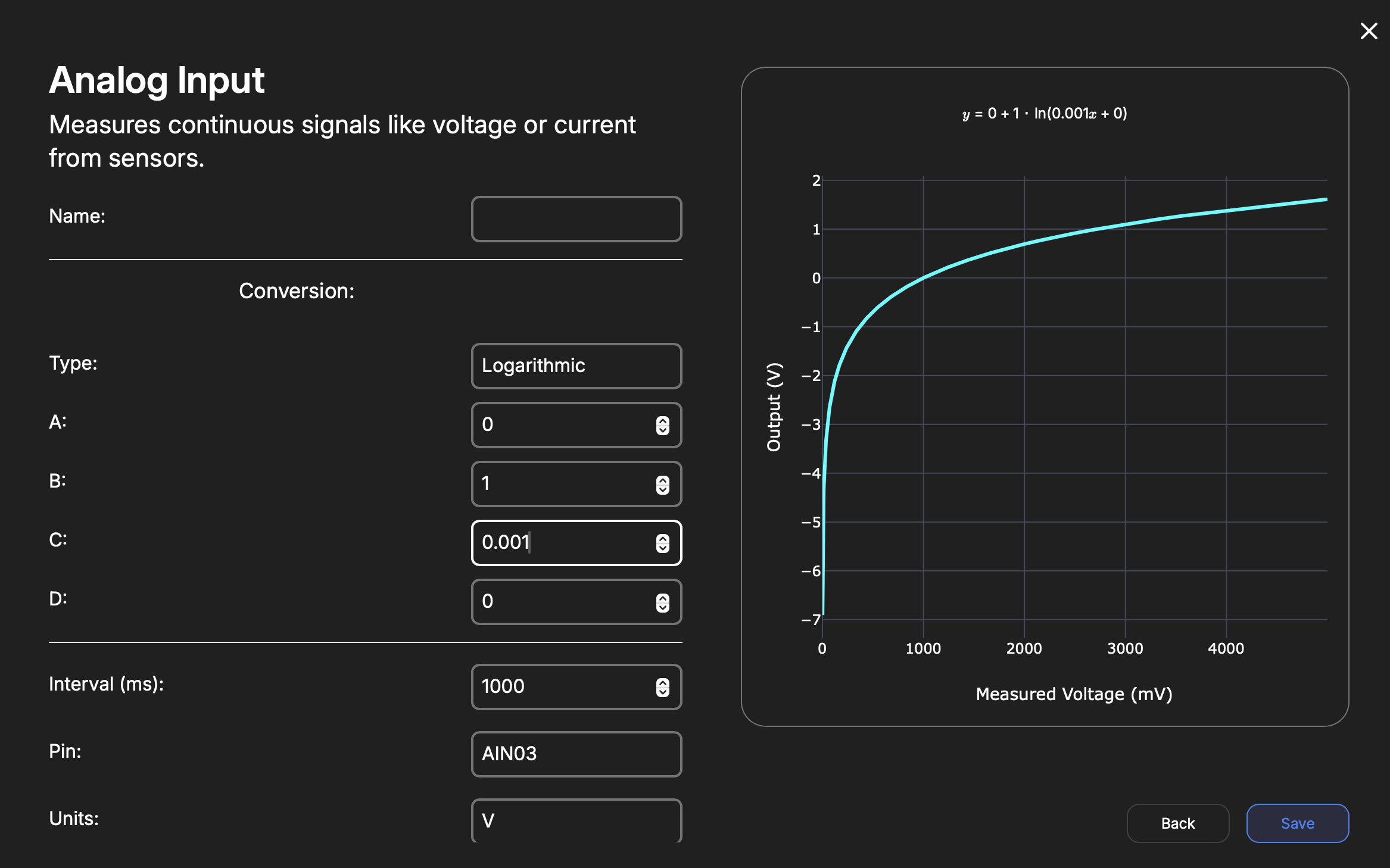
Analog Input
| Key | Type | Description |
|---|---|---|
| Name | String | Internal reference to task. |
| Type | Enum | Polynomial Logarithmic |
| A | Float | Conversion equation A coefficient |
| B | Float | Conversion equation B coefficient |
| C | Float | Conversion equation C coefficient |
| D | Float | Conversion equation D coefficient |
| Unit | String | Indicates unit of measurement. |
| Interval | Interval | Rate in milliseconds the task publishes a measurement to MQTT. |
| Pin | Enum | Chosen Analog Input Pin (AIN00-AIN07). |
| Comment | String | Comment to help user understand what this service is about. |
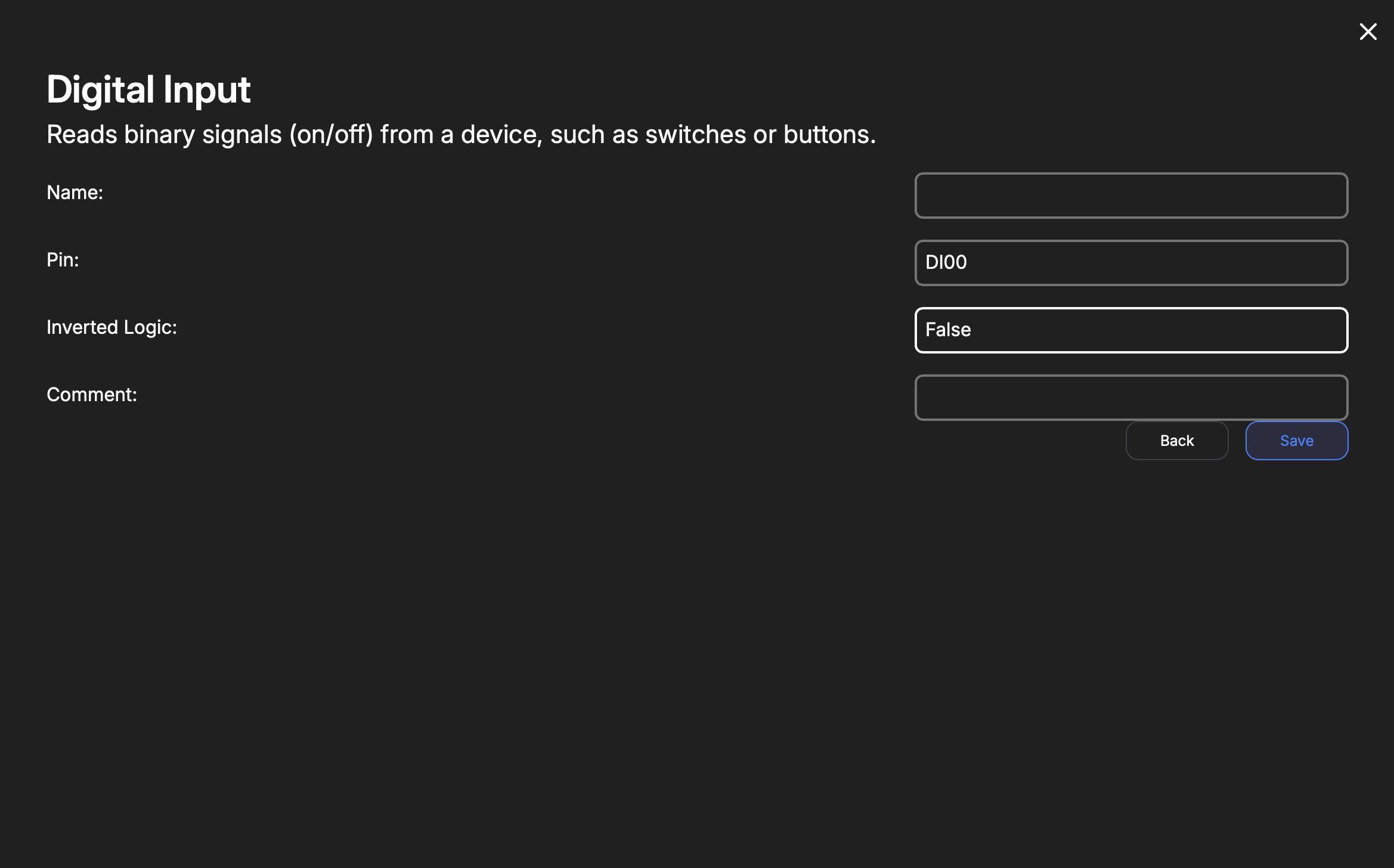
Digital Input
| Key | Type | Description |
|---|---|---|
| Name | String | Internal reference to task. |
| Pin | Enum | DI00 - DI15 |
| Inverted Logic | Boolean | Is the input an active-high? Set to false. Otherwise, set to true. |
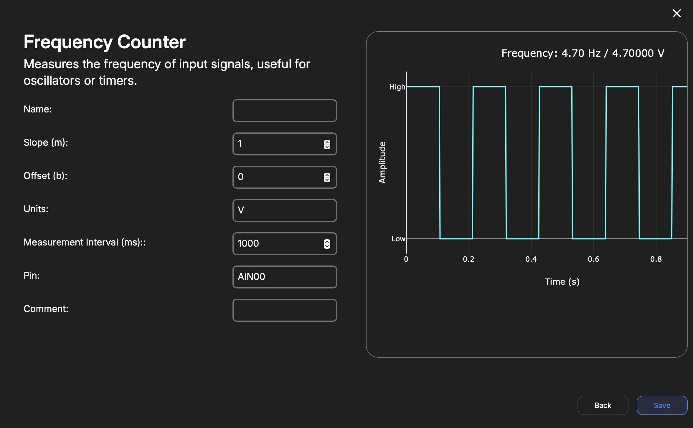
Frequency Counter
| Key | Type | Description |
|---|---|---|
| Name | String | Internal reference to task. |
| Slope | Float | Y = mX + b, m = Slope, x = millivolts measured.This is used to provide unit conversion (e.g. turning mV to PSI). The user determines this. The output, “Y”, is the unit-converted reading. |
| Offset | Float | mV to unit zero-offset. ‘b’ in the above equation. |
| Unit | String | Indicates unit of measurement. |
| Interval | Interval | Rate in milliseconds the task publishes a value to MQTT. |
| Pin | Enum | Chosen Digital or Analog Input Pin (AIN00-AIN07, DI0-DI5). |
Analog Output
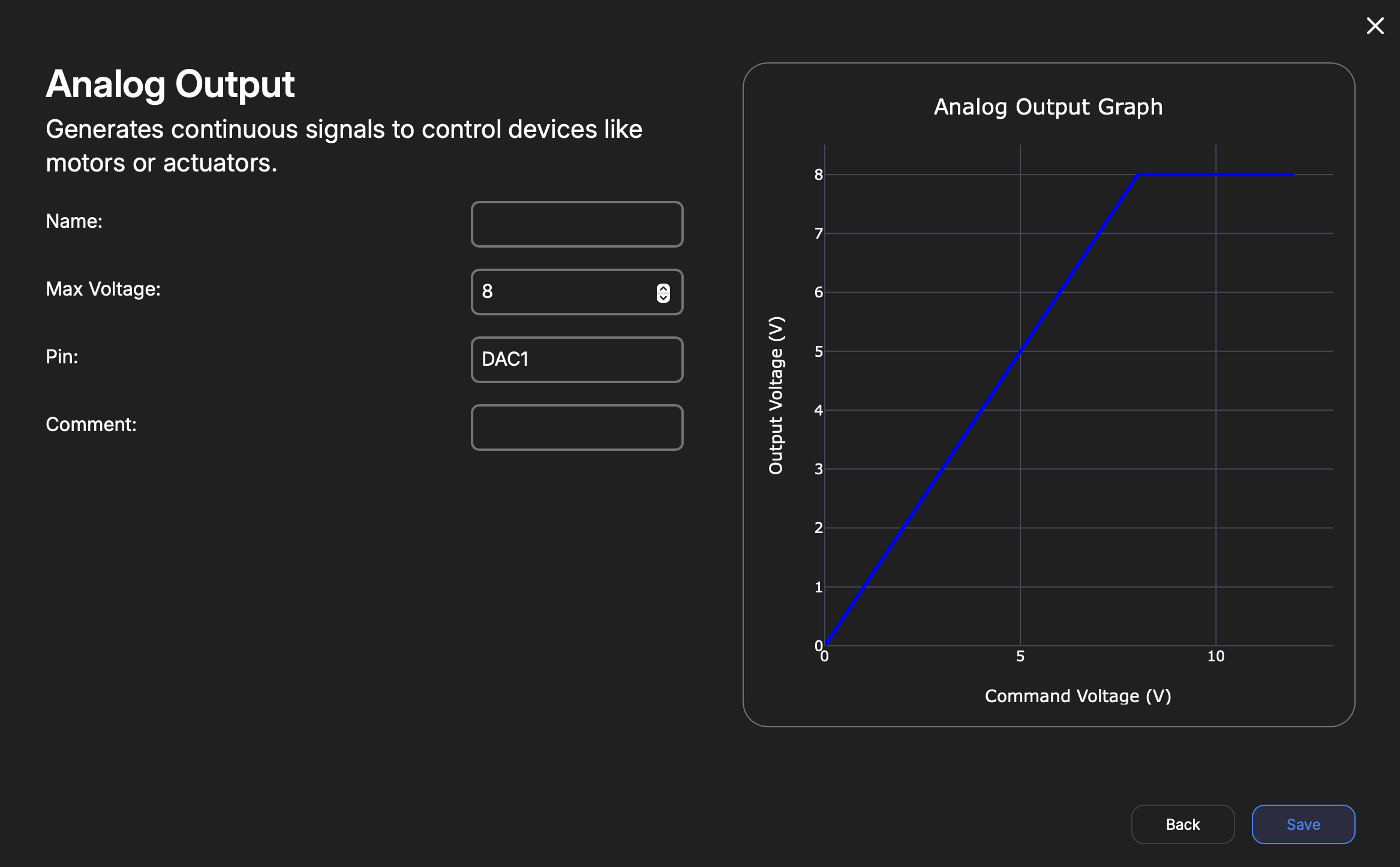
The user can move the jumper labeled
DAC VCCto either use 5V or 12V to set a hardware limit. Do this only with the DAQAstra powered off.
| Key | Type | Description |
|---|---|---|
| Name | String | Internal reference to task. |
| Max Voltage | Float | A software upper-limit on voltage that the DAC will output. Maximum is 12VDC. |
| Pin | Enum | [DAC1, DAC2] |
Digital Output
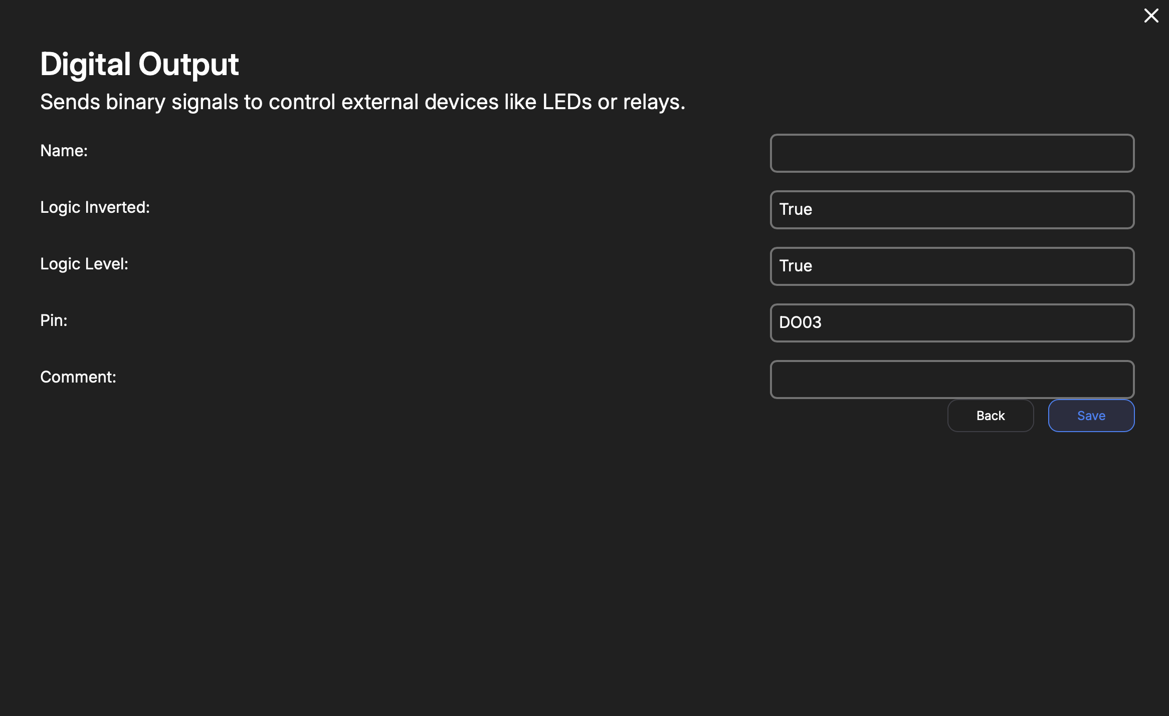
| Key | Type | Description |
|---|---|---|
| Name | String | Internal reference to task. |
| Logic Level | Boolean | The logic-level at boot. |
| Logic Inversion | Bool | Whether the command logic should be inverted. True means logic-low is 'on'. |
| Pin | Enum | DO00-DO09, RELAY0-RELAY3 |
PWM Output
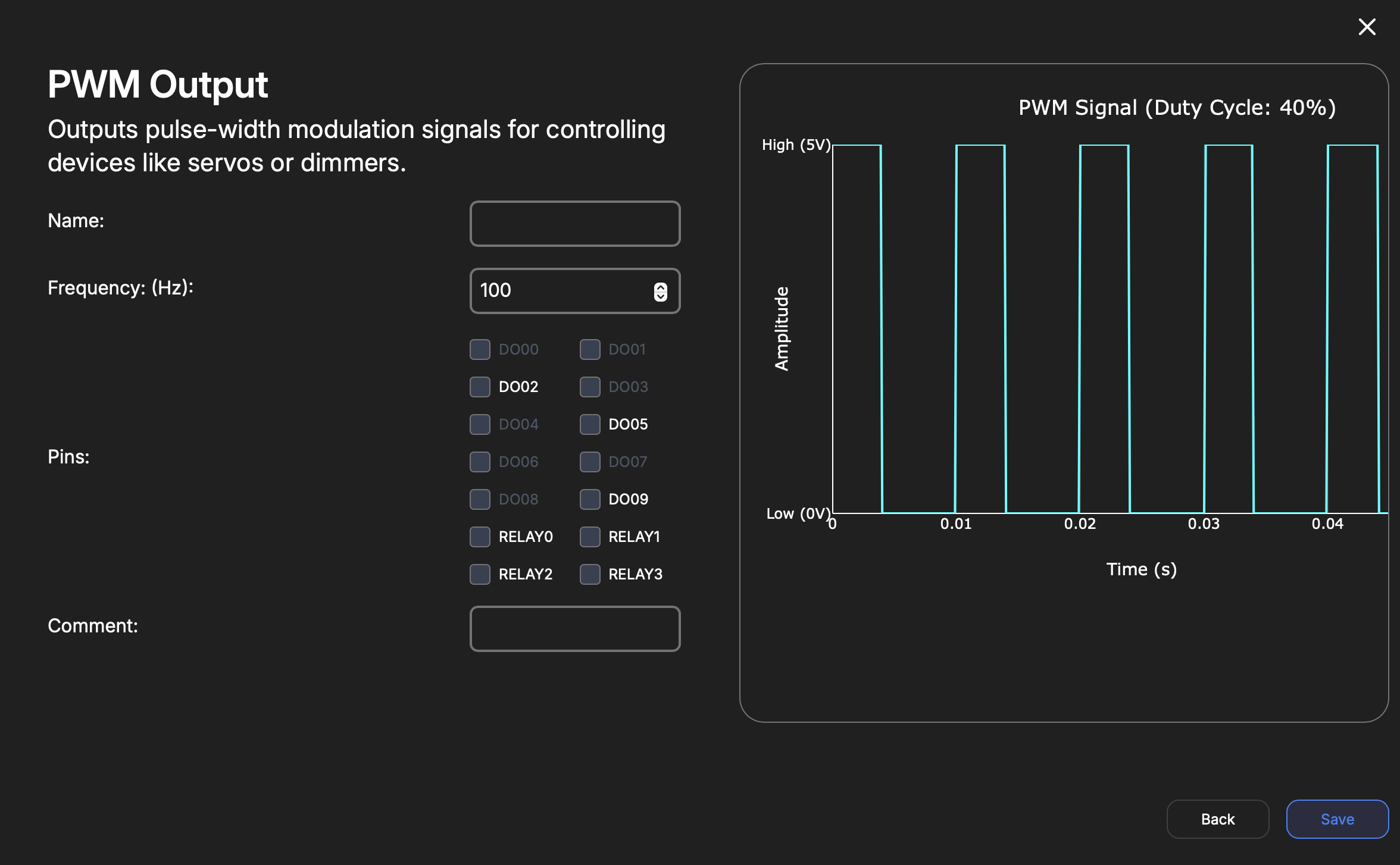
| Key | Type | Description |
|---|---|---|
| Name | String | Internal reference to task. |
| Frequency | Number | Default PWM frequency at boot. |
| Pin | Array(Enum) | Multi-select of pins desired to be under PWM control. Options are all available Digital Outputs and Relay pins. |
Complementary PWM
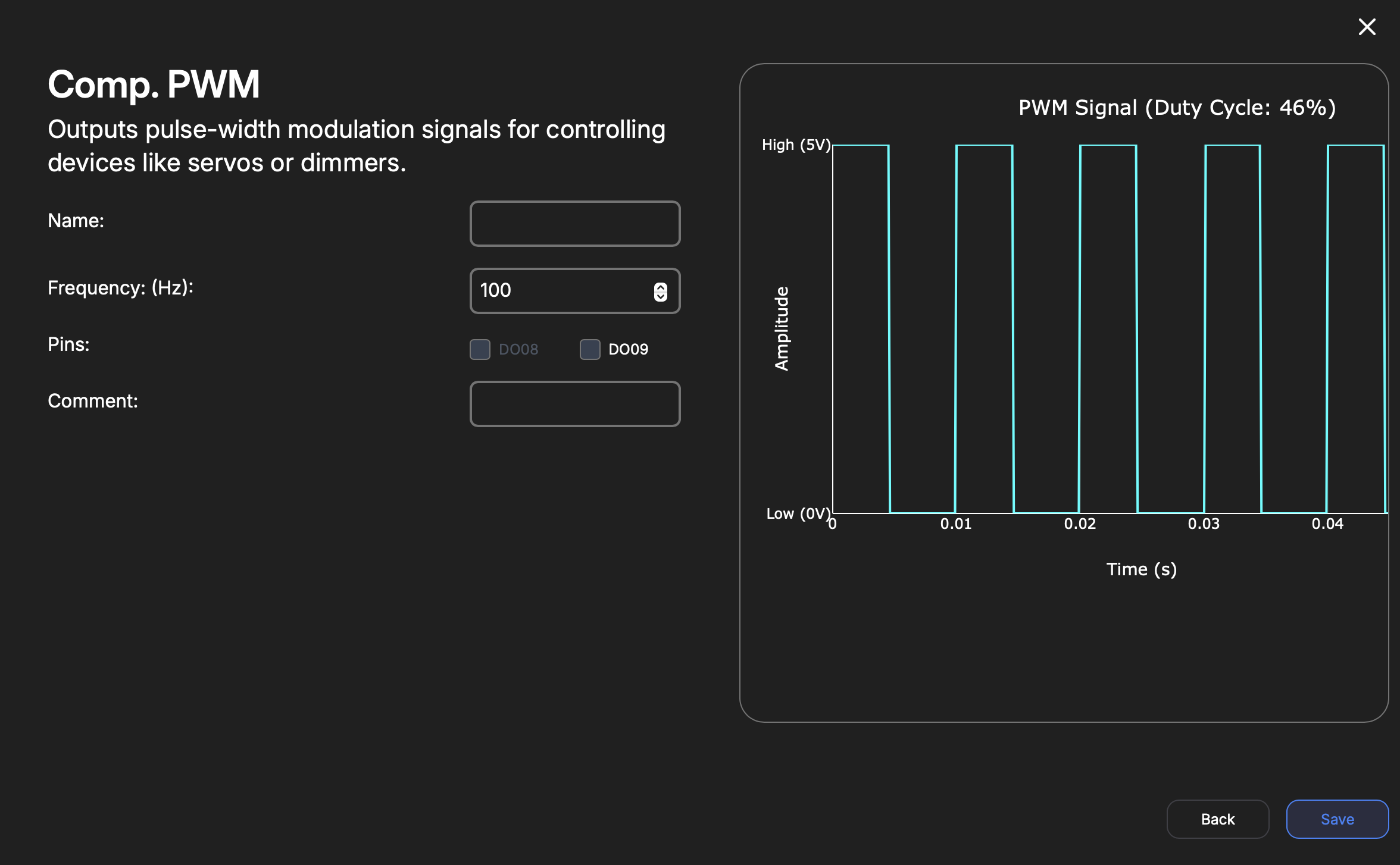
| Key | Type | Description |
|---|---|---|
| Name | String | Internal reference to task. |
| Frequency | Number | Default PWM frequency at boot. |
| Pin | Array(Enum) | Multi-select of pins desired to be under Complementary PWM control. DO08 and DO09 are the available complementary pins. |
Command
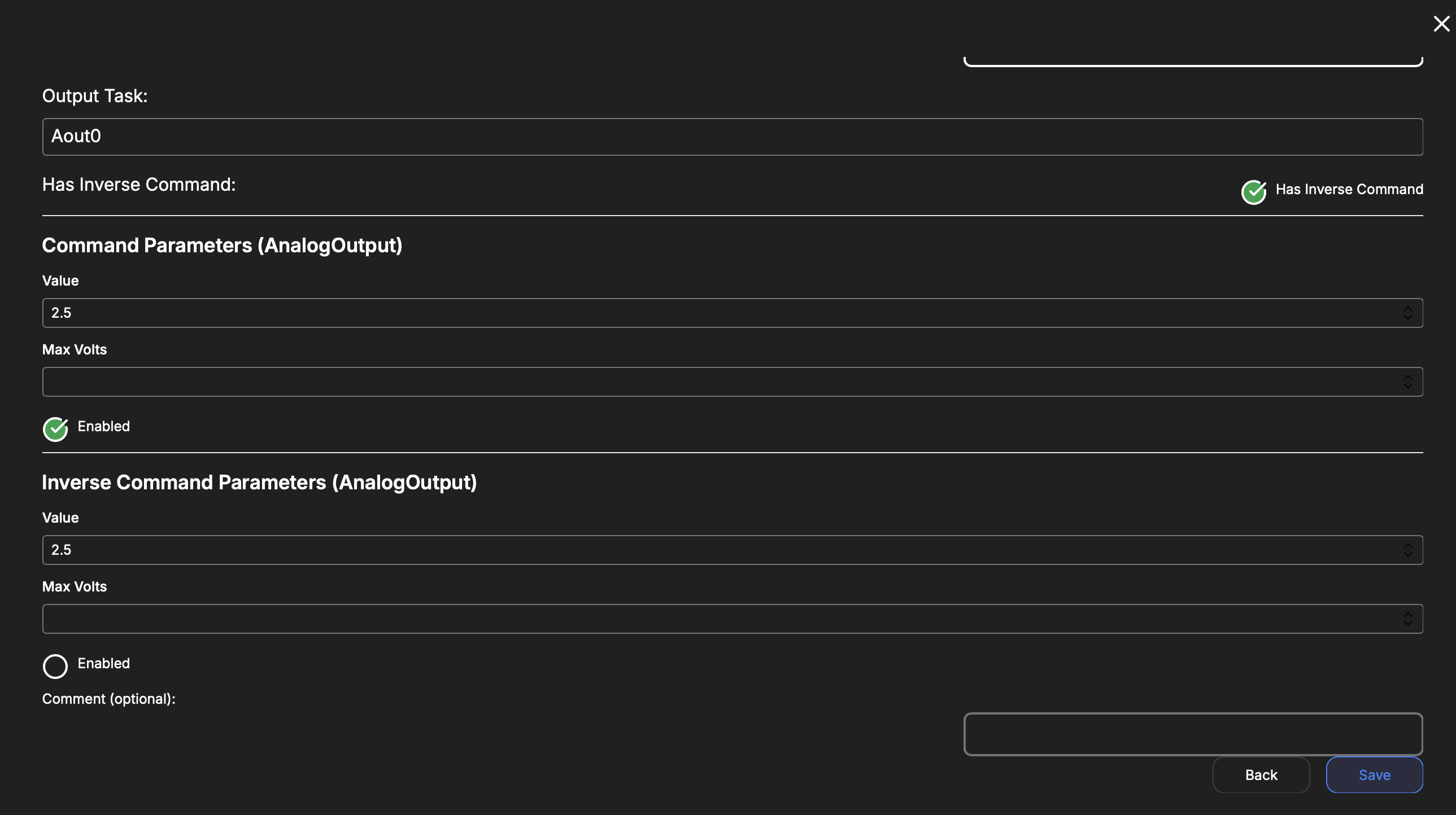
| Key | Type | Description |
|---|---|---|
| Name | String | Internal reference to task. |
| Output Task | String | Selection of a valid (already-defined) services that can receive a command. |
| Has Inverse Command | Boolean | Whether a different command should be sent when false is received by this service. enables Inverse Command Parameters. |
| Command Parameters | Object | Changes depending on Output Tasks. This is the set of parameters you can change in the target service. |
| Inverse Command Parameters | Object | This is the same as Command Parameters but will be sent instead when this service receives a false message. |
Math Channel
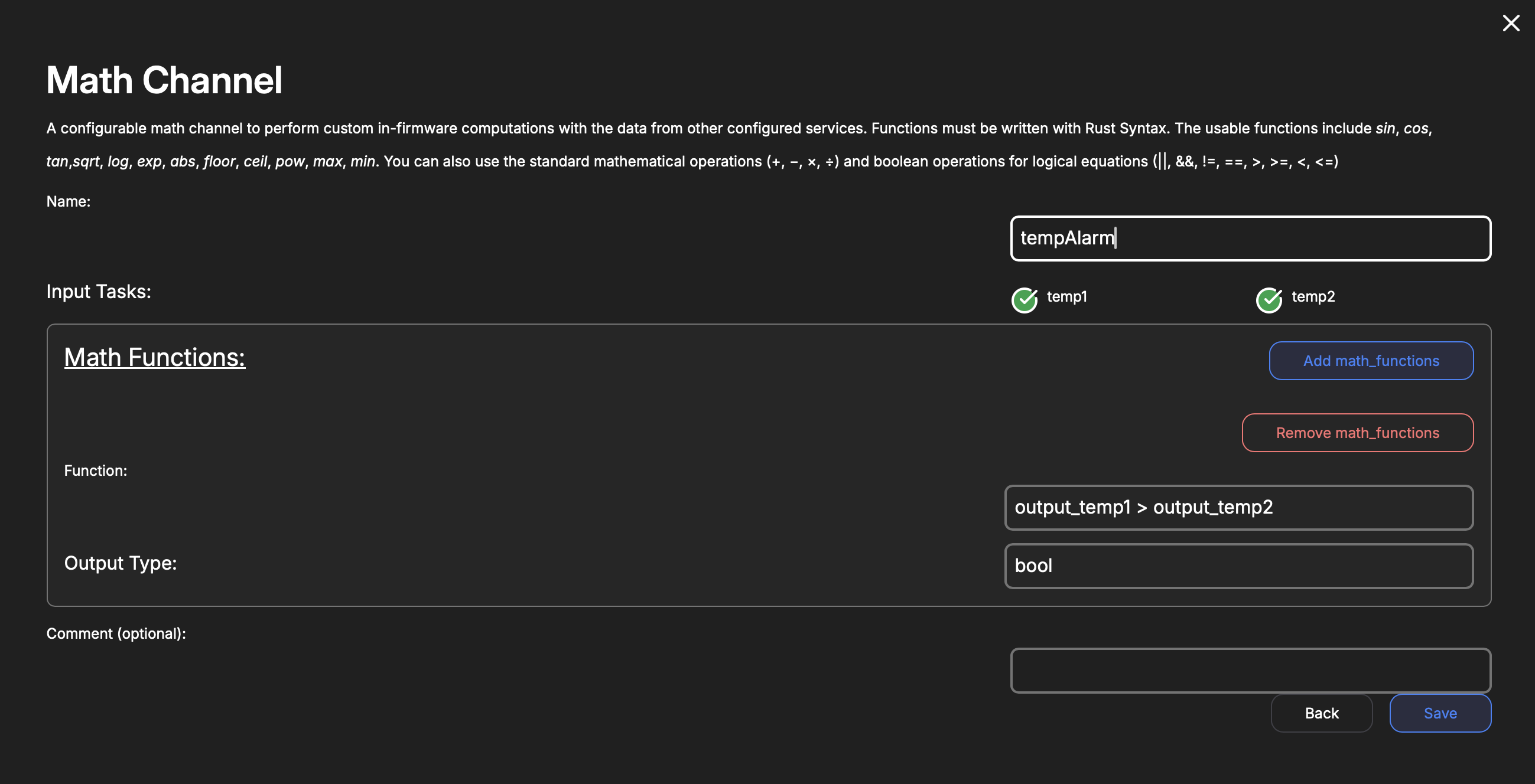
A configurable math channel to perform custom in-firmware computations with the data from other configured services. Functions must be written with Rust Syntax. The usable functions include sin, cos, tan,sqrt, log, exp, abs, floor, ceil, pow, max, min. You can also use the standard mathematical operations (+, −, ×, ÷) and boolean operations for logical equations (||, &&, !=, ==, >, >=, <, <=)
| Key | Type | Description |
|---|---|---|
| Name | String | Internal reference to task. |
| Input Tasks | Array(String) | A list of other defined services that provide a valid numeric input as a variable in the math functions. |
| Math Functions | Array(Object) | Each function contains an expression & an output type. If a logical function is used and results in true or false, choose bool. Otherwise use f32. The selection of input tasks will autofill the appropriate variable name for that input into a new function. You may use multiple input tasks in a single function, just copy the generated variable name into where it should be used. |
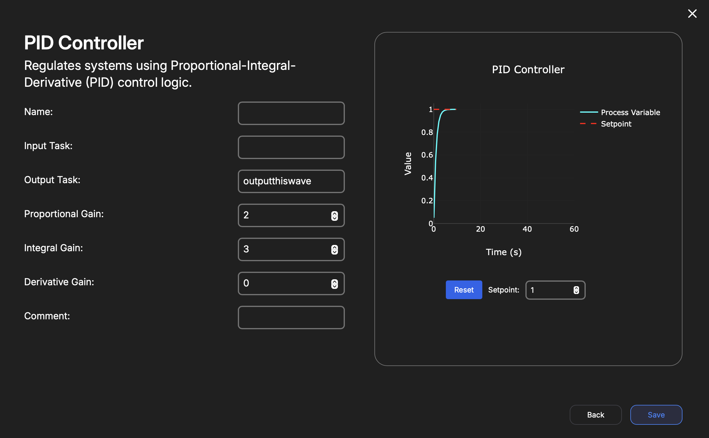
PID Controller
| Key | Type | Description |
|---|---|---|
| Name | String | Internal reference to task. |
| Input Task | String | The Name of an already defined task that is capable of acting as a PID input. These are Analog-Inputs and Thermocouples for now. |
| Output Task | String | The Name of an already defined task that is capable of acting as a PID control output. This includes PWM channels and Analog-Outputs. |
| Proportional Gain | Number | Default PID Kp at boot. |
| Integral Gain | Number | Default PID Ki at boot. |
| Derivative Gain | Number | Default PID Kd at boot. |
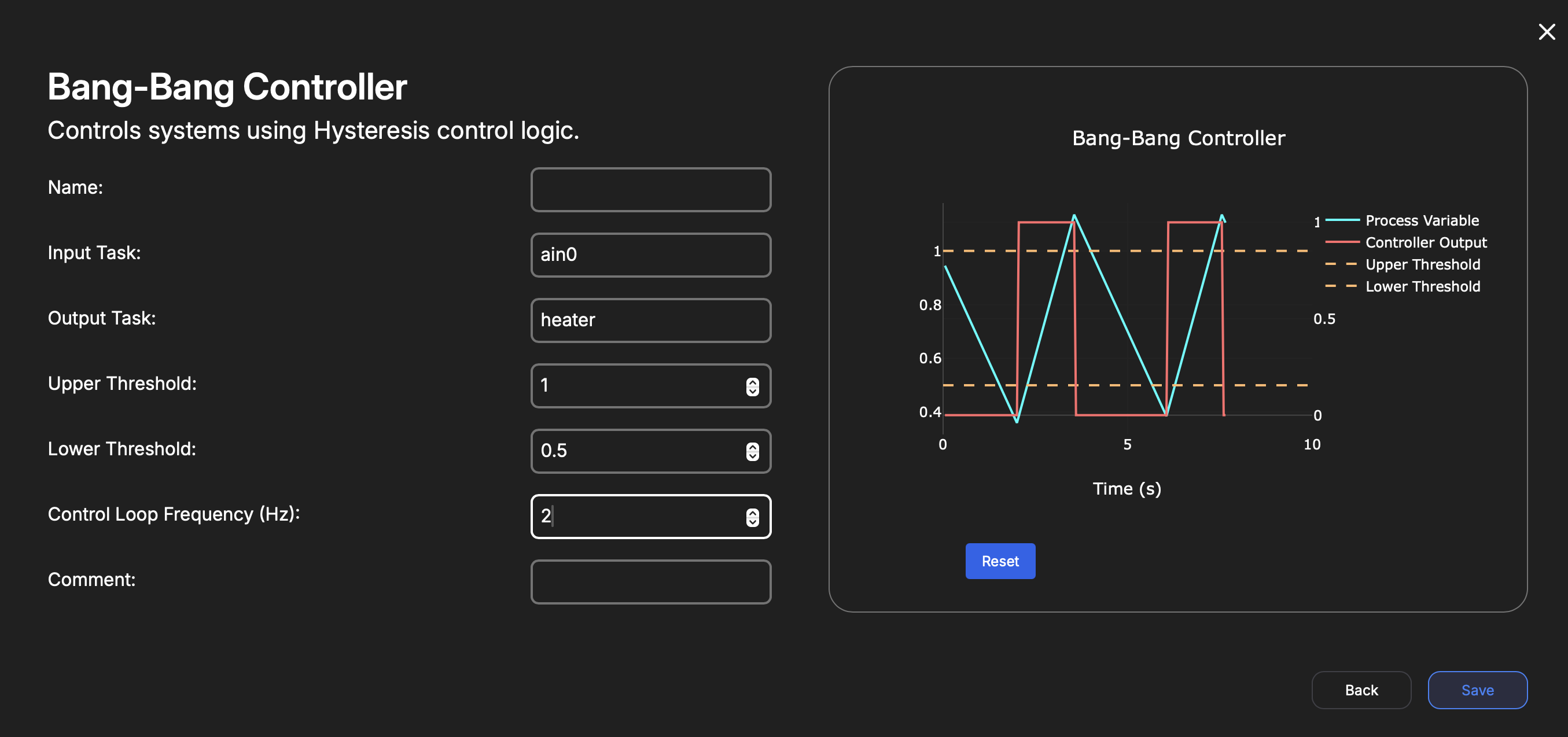
Bang-Bang Controller
| Key | Type | Description |
|---|---|---|
| Name | String | Internal reference to task. |
| Input Task | Enum | Data to use as feedback for the controller. Can come from Analog Input, Thermocouple, ADS7953. |
| Output Task | Enum | Output the controller will modulate. Can choose a Digital Output or PDU channel. |
| Upper Threshold | Number | Upper hysteresis limit for the controller. |
| Lower Threshold | Number | Lower hysteresis limit for the controller. |
| Control Loop Frequency | Number | The rate at which the controller will update the state of the output. If the Input Task updates faster than this rate, the input values will be averaged. |
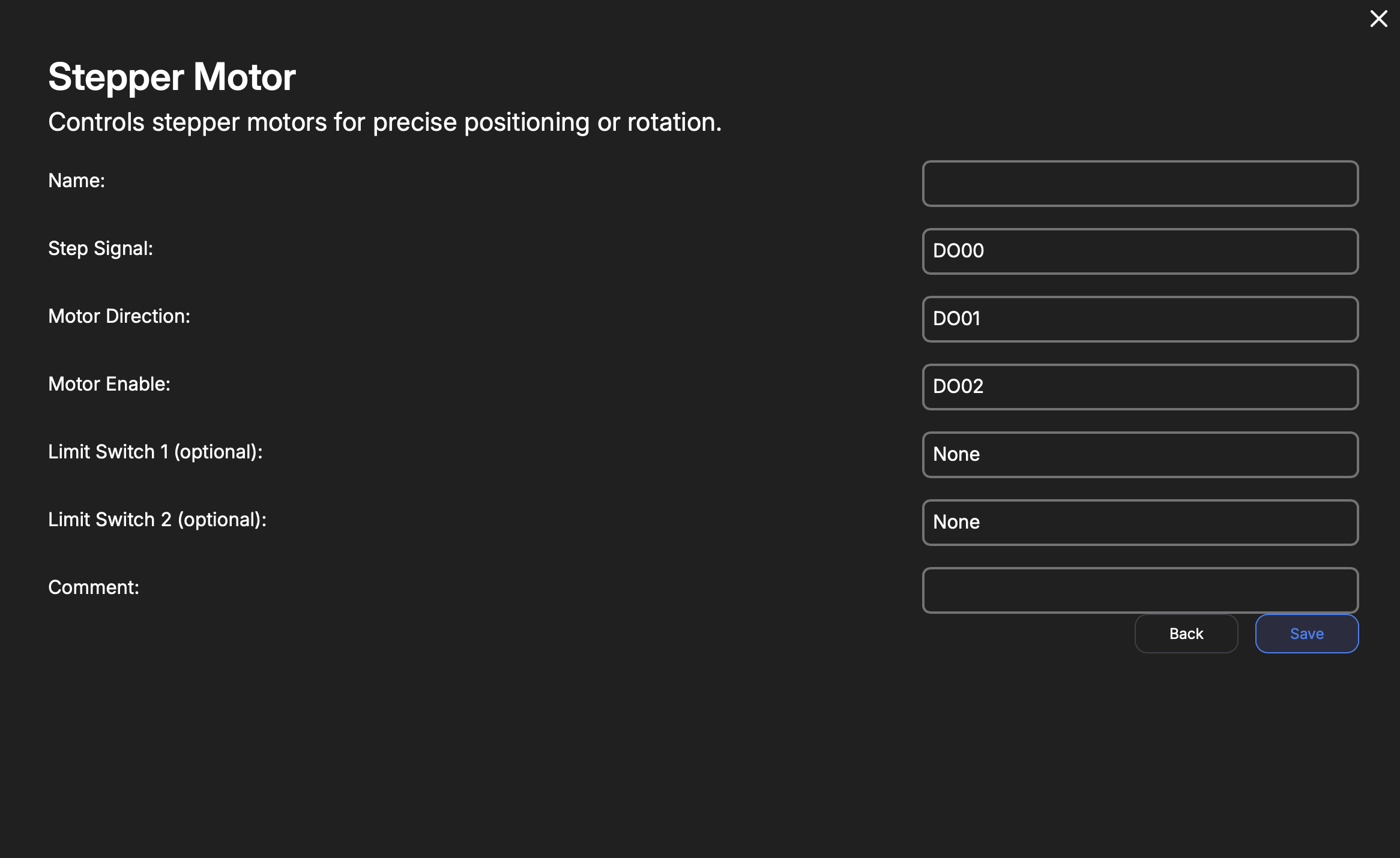
Stepper Motor
| Key | Type | Description |
|---|---|---|
| Name | String | Internal reference to task. |
| Step Signal | Enum | Output pin for the stepper-motor 'pulse' or step. |
| Motor Direction | Enum | Output pin for the stepper-motor direction signal |
| Motor Enable | Number | Output pin for stepper-motor enable. This powers the motor phases. |
| Limit Switch 1 | Enum or Null | Digital input for wiring an optional limit switch that will interrupt a move command. |
| Limit Switch 2 | Enum or Null | Digital input for wiring an optional limit switch that will interrupt a move command. |
Actuator
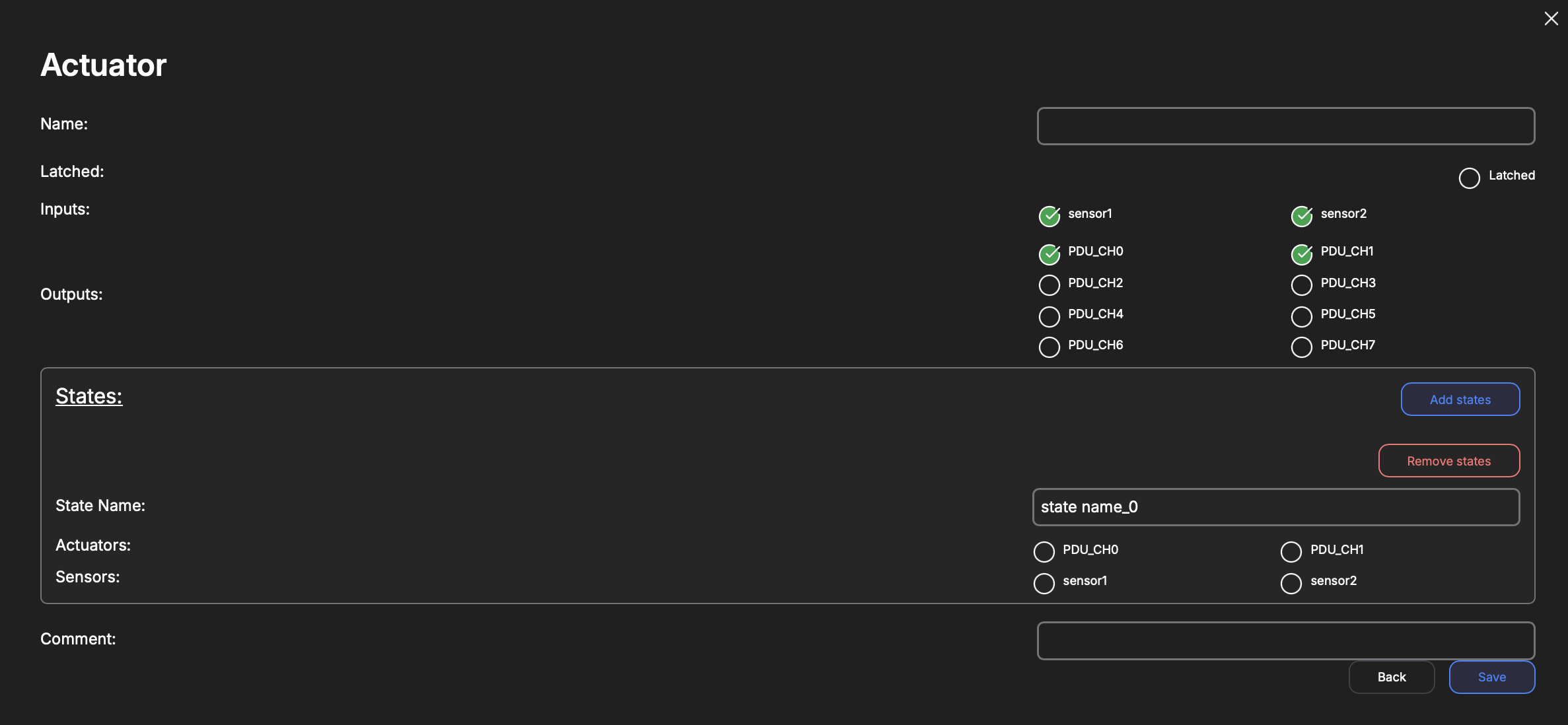
This is a more naive implementation of
Stateful Actuator. There is no enforcement of how the actuator enters or exits a state. This is really meant as a tool to automate a group of inputs and outputs with very simple states (on/off) and that do not require the traversal of multiple states to execute an action. If this is needed, useStateful Actuator.
| Key | Type | Description |
|---|---|---|
| Name | String | Internal reference to task. |
| Latched | Boolean | Whether this actuator latches the outputs upon executing a command. |
| Inputs | Array | A multi-select of already-configured (compatible) inputs to the Stateful Actuator Service. In this case, we have two Digital-Input services that are used. Analog-Input may be used as well. |
| Outputs | Array | A multi-select of already-configured (compatible) outputs for the Stateful Actuator Service. In this case, we have a PDU service defined. One may use Digital-Outputs too. |
| States | Array | User-defined names attached to certain combinations of the chosen Inputs' logic-levels and chosen Outputs commands that ought to result in this state's Inputs levels. |
Actuator States
| Key | Type | Description |
|---|---|---|
| Name | String | User defined name attached to the specific state of the inputs. |
| Actuators | Array of Booleans | The logic-levels that the service will command to each configured output to cause this transition. |
| Sensors | Array of Booleans | The state of the Inputs that are associated with this State name. |
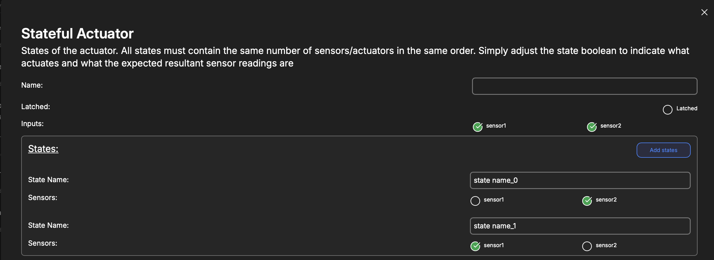
Stateful Actuator
| Key | Type | Description |
|---|---|---|
| Name | String | Internal reference to task. |
| Latched | Boolean | Whether this actuator latches the outputs upon executing a command. |
| Inputs | Array | A multi-select of already-configured (compatible) inputs to the Stateful Actuator Service. In this case, we have two Digital-Input services that are used. Analog-Input may be used as well. |
| States | Array | User-defined names attached to certain combinations of the chosen Inputs' logic-levels. |
| Outputs | Array | A multi-select of already-configured (compatible) outputs for the Stateful Actuator Service. In this case, we have a PDU service defined. One may use Digital-Outputs too. |
| Transitions | Array | User-defined state transitions. |
| Sequences | Optional Array | User-defined automation sequences with configured in-firmware triggers. Convenience method. |
States
It is recommended that the configured states cover all possible combinations of states of the chosen inputs.
| Key | Type | Description |
|---|---|---|
| Name | String | User defined name attached to the specific state of the inputs. |
| Sensors | Array of Booleans | The state of the Inputs that are associated with the given name. |
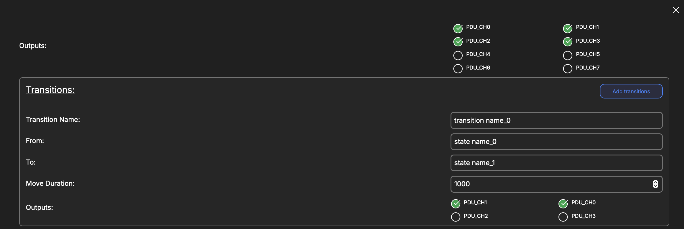
Transitions
| Key | Type | Description |
|---|---|---|
| Name | String | User defined name attached to the specific state of the inputs. |
| From | Enum | Chose a defined State from which this transition may be triggered. |
| To | Enum | Chose a defined State to which this transition is expected to result in. |
| Move Duration | Int | Duration in milliseconds that may elapse before this transition times out. |
| Outputs | Array of Booleans | The logic-levels that the service will command to each configured output to cause this transition. |
Sequences
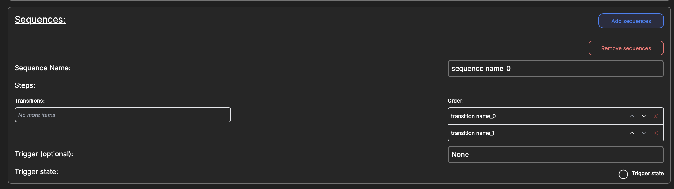
Consider a trigger as an in-firmware emergency-stop.
| Key | Type | Description |
|---|---|---|
| Name | String | User defined name attached to the automation sequence. |
| Steps | Array | Chose and order defined Transitions this sequence should attempt. |
| Trigger | Optional Enum | Choose an already-configured (but not used in this service) Analog-Input or Digital-Input that this sequence should track the state of. |
| Trigger State | Boolean | The state of the configured Trigger that ought to begin this sequence. |
IMU (MPU6050)
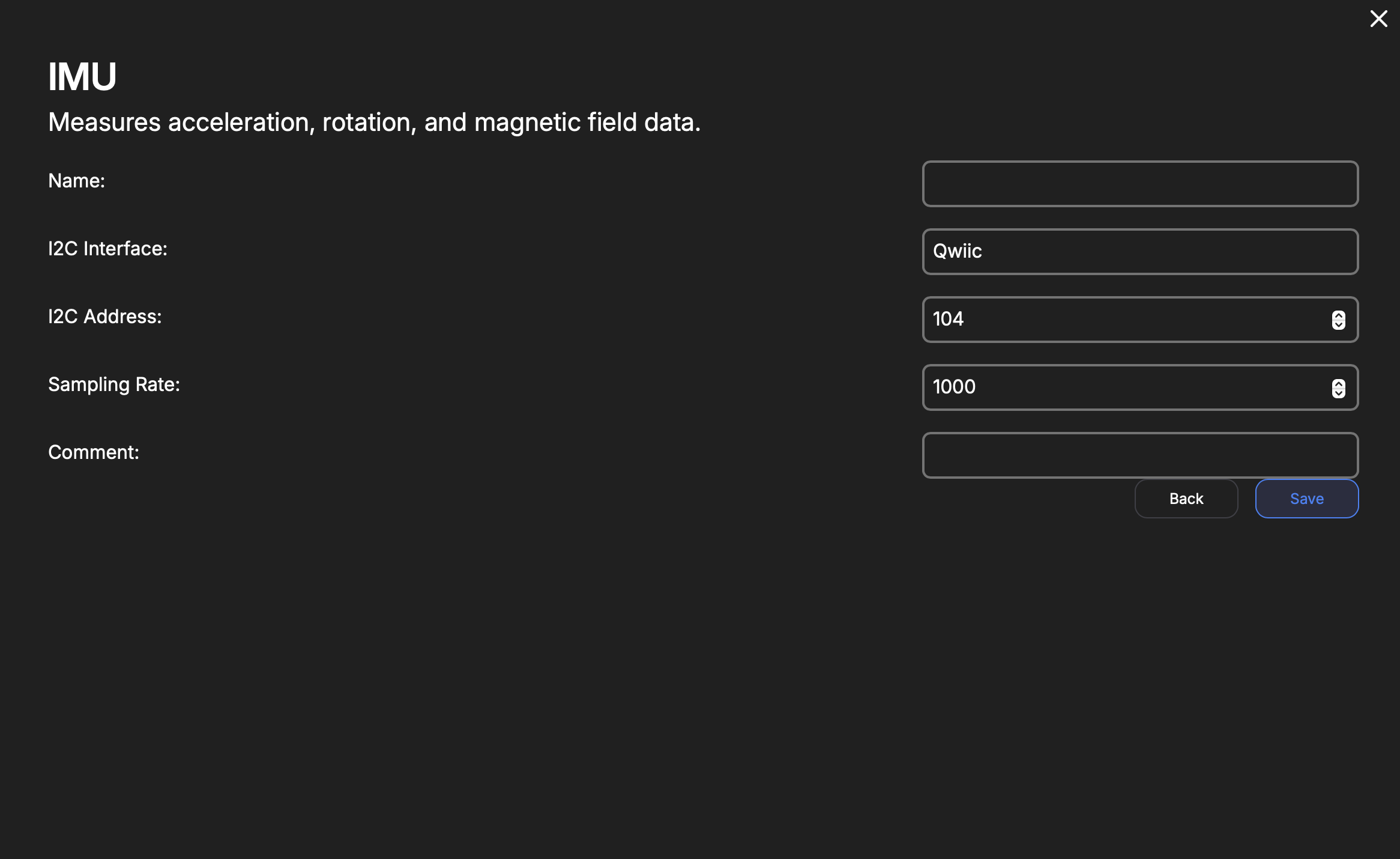
| Key | Type | Description |
|---|---|---|
| Name | String | Internal reference to task. |
| I2C Interface | Enum | Qwiic or MikroBus I2C interface. |
| I2C Address | Number | I2C Bus address for the MPU6050. Default is 104. Do not change unless the address is changed on the MPU6050, beforehand. |
| Sampling Rate | Number | Duration, in milliseconds, to sample and send data from the MPU6050. |
Magnetometer (QMC5883L)
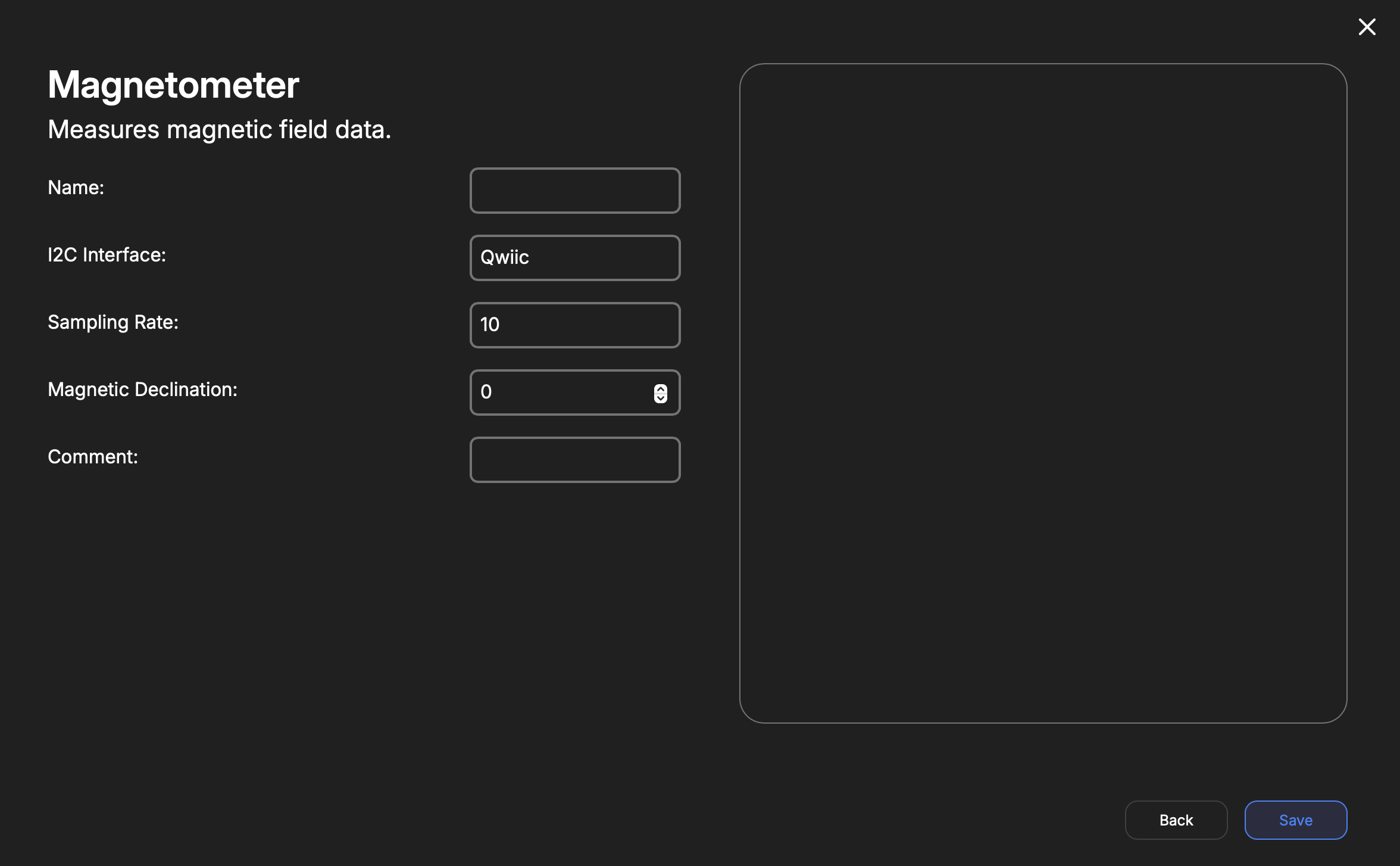
| Key | Type | Description |
|---|---|---|
| Name | String | Internal reference to task. |
| I2C Interface | Enum | Qwiic or Mikrobus interface used. |
| Sampling Rate | Enum | 10, 50, 100, or 200 Sa/s |
| Magnetic Declination | Number | The angular offset of magnetic North from true North at your location. This orients the magnetic compass to treat zero degrees as true North. |
IR Camera (MLX90640)
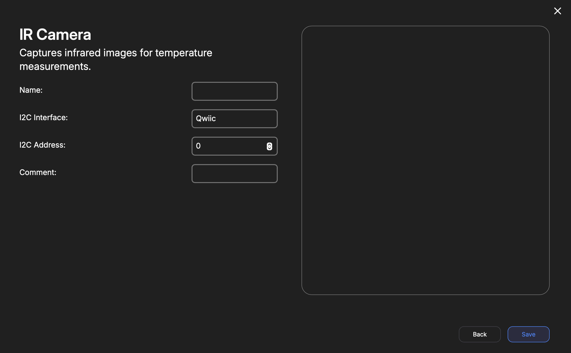
| Key | Type | Description |
|---|---|---|
| Name | String | Internal reference to task. |
| I2C Interface | Enum | Qwiic or Mikrobus interface used. |
| I2C Address | Number | I2C address of MLX90640 IR-camera. Default is 51 (0x33). This field is in decimal, not hex. |
Thermocouple (MAX31855)
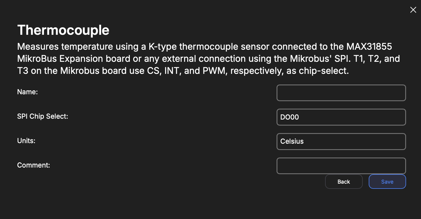
| Key | Type | Description |
|---|---|---|
| Name | String | Internal reference to task. |
| SPI Chip Select | Enum | DO Pins or MikroBus I/O. The expansion board provided by TransAstra uses MikroBus CS, INT, and PWM for T1, T2, and T3, respectively. |
| Units | Enum | Celsius, Fahrenheit, or Kelvin |
Load Cell (HX711)
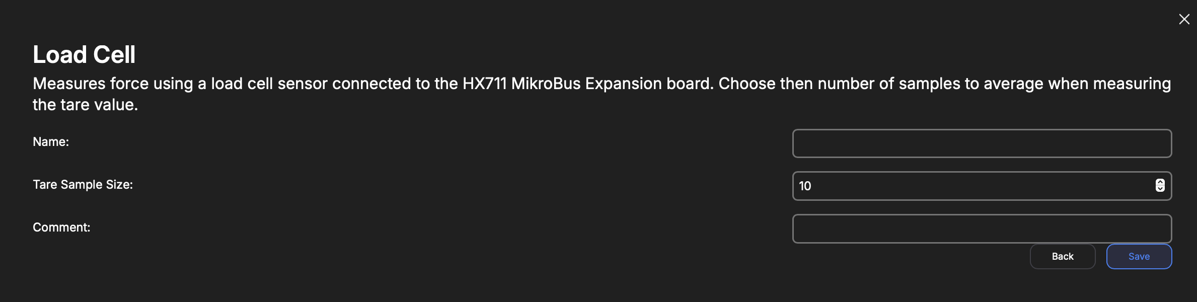
Uses MikroBus SCK and MISO by default for the HX711 data interface.
| Key | Type | Description |
|---|---|---|
| Name | String | Internal reference to task. |
| Tare Sample Size | Int | Number of samples to use when measuring a tare value. |
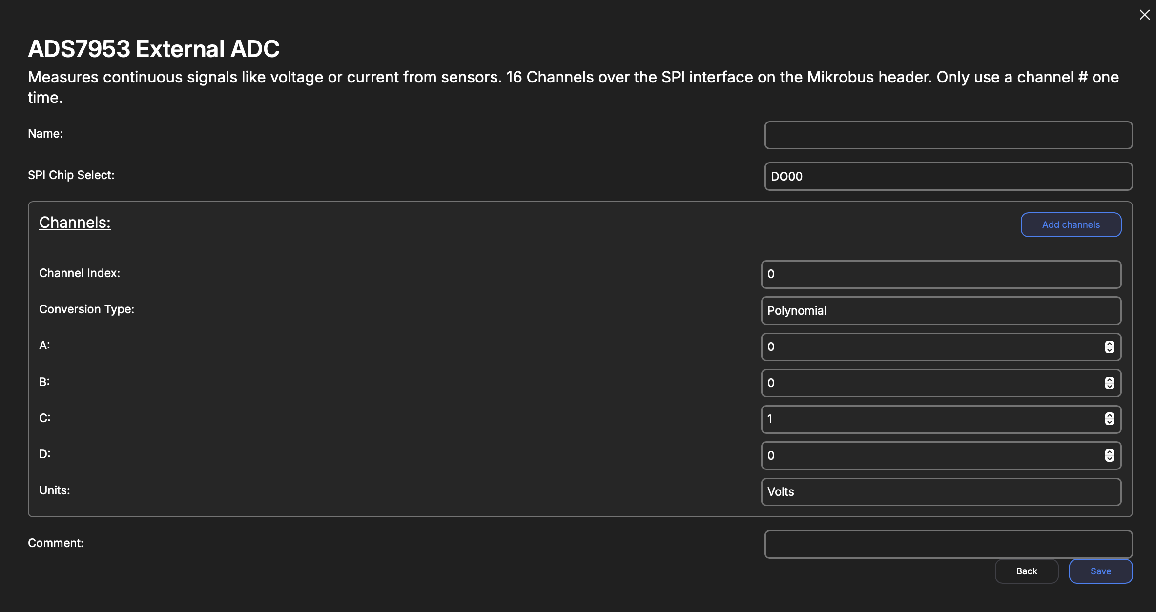
ADS7953
| Key | Type | Description |
|---|---|---|
| Name | String | Internal reference to task. |
| SPI Chip Select | Enum | DO Pins or MikroBus I/O. |
| Channels | Array | An array of Channel objects. Each object corresponds to the conversion and units for a given input to the ADS7953 chip. |
Channel
| Key | Type | Description |
|---|---|---|
| Channel Index | Int | A value 0-15, corresponds to the input on the ADS chip. |
| Type | Enum | Polynomial Logarithmic |
| A | Float | Conversion equation A coefficient |
| B | Float | Conversion equation B coefficient |
| C | Float | Conversion equation C coefficient |
| D | Float | Conversion equation D coefficient |
| Unit | String | Indicates unit of measurement. |
Power-Distribution Unit (PDU)
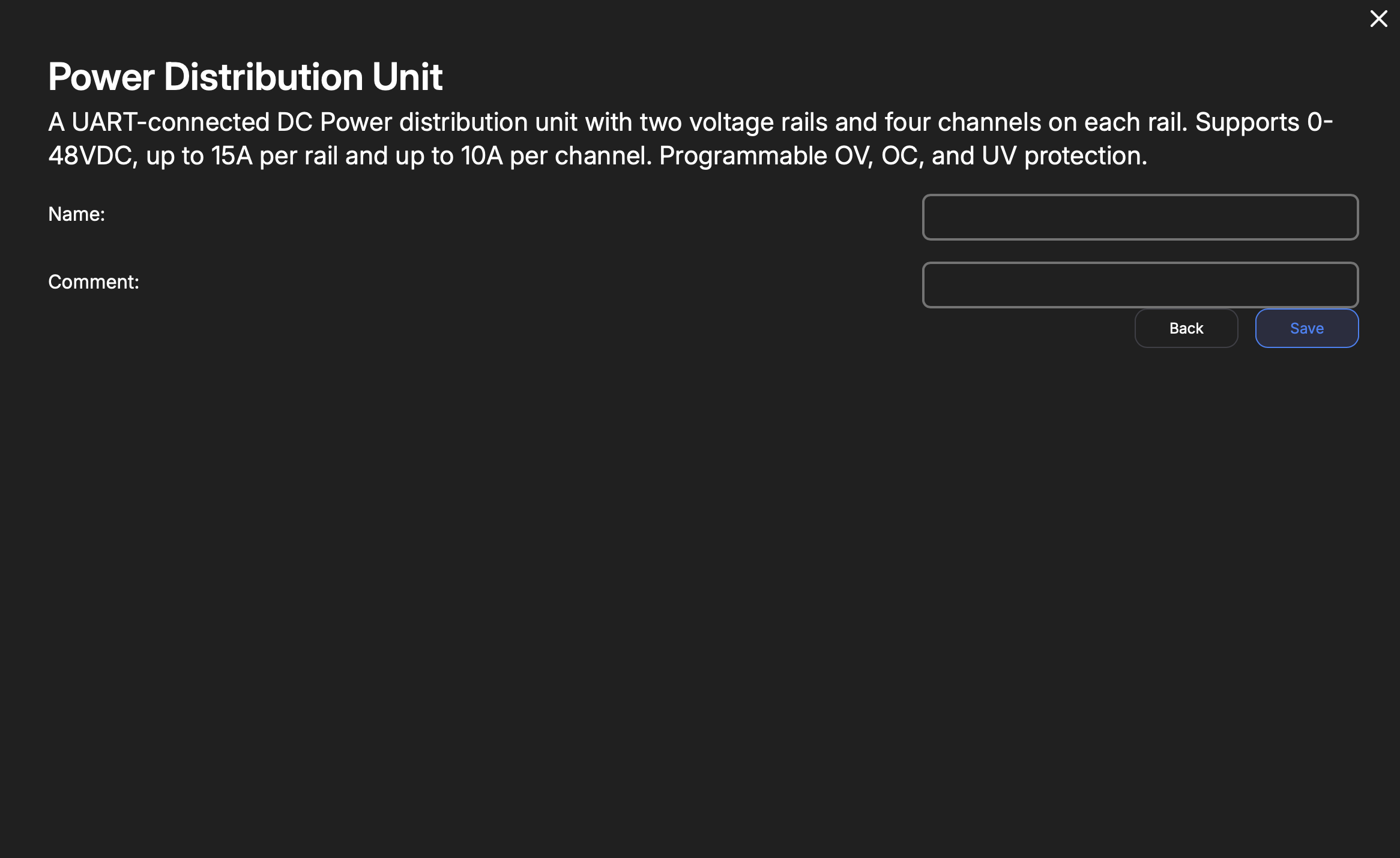
The PDU board will connect to the UART RX & TX pins on the DAQAstra's SuperSeal connector.
| Key | Type | Description |
|---|---|---|
| Name | String | Internal reference to task. |